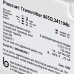
Pressure Transmitter
Series: 985
BENEFITS
The 985 series is a family of compact differential pressure transmitters (IP65) designed to measure differential pressure, overpressure and vacuum in air and other non‑combustible, non‑aggressive gases. Depending on the version, the devices offer up to 8 selectable pressure ranges and provide analogue output signals for easy integration into HVAC and building automation systems. The range can be adapted on site using jumpers (985M/985A) or a rotary selector switch (985Q).
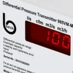
For advanced applications, optional functions include square‑root output for volume‑flow calculations from differential pressure, an adjustable transistor switching output, and an optional red LED display for local readout. For digital building integration, the 985‑Modbus variants add Modbus RTU (RS‑485) communication and full parameterisation via fieldbus. The 985V variants are designed specifically for volume flow or flow velocity, with menu‑guided configuration and the ability to switch between flow/velocity and pressure measurement.
Application Details
Building automation / HVAC
- Differential pressure measurement for air handling units (AHUs) and ventilation systems
- VAV applications: airflow control and monitoring (pressure‑independent VAV terminal units)
- Duct static pressure control: fan speed optimisation and demand‑based ventilation
- Filter monitoring: clogging detection and maintenance based on pressure drop
- Fan / blower monitoring: performance and operating status supervision
Cleanrooms & laboratories
- Room pressure monitoring and pressure cascades between zones (positive/negative pressure)
- Overpressure monitoring in cleanrooms, laboratories and controlled environments
- Pressure stability monitoring for contamination control and process safety
Flow / velocity measurement (985V and 985‑Modbus)
- Volume flow or flow velocity measurement from differential pressure using k‑factor or reference setup
- HVAC duct or plenum flow measurement for commissioning, balancing and continuous monitoring
- Applications where square‑root scaling is needed for DP‑based flow calculations
Pressure ranges
Measured variables (depending on type)
- Differential pressure, overpressure, vacuum
- Optional: volume flow / flow velocity (985V / 985‑Modbus)
Medium
- Air and non‑combustible, non‑aggressive gases
Measuring principle
- Piezoresistive pressure transducer
Pressure ranges (family overview)
- Very low ranges down to ±25 Pa (model‑dependent)
- Wide range selection up to 100 kPa / 1 bar (model‑dependent)
- 985V / 985V‑Modbus: ranges from 0…50 Pa up to 0…10 kPa (further ranges on request)
Range selection
- 985M / 985A: up to 2 selectable ranges (jumper)
- 985Q: up to 8 selectable ranges (rotary switch)
- 985‑Modbus: parameterised via Modbus RTU
- 985V: flow/velocity vs pressure selectable by jumper; menu‑guided setup
Outputs / interfaces
- 3‑wire: 0…10 V or 4…20 mA (selectable by jumper, depending on version)
- 2‑wire: 4…20 mA (985M option)
- Digital: Modbus RTU (RS‑485) on 985‑Modbus variants
Optional functions (model‑dependent)
- Square‑root output (for flow from differential pressure)
- Adjustable transistor switching output (e.g., NPN NO; other logic on request; not on 2‑wire versions)
- Red LED display (typically on 3‑wire / display variants)
Power supply (typical)
- 2‑wire versions: 18…30 VDC
- 3‑wire versions: 18…30 VAC/VDC (50–60 Hz), depending on model
Operating temperature (varies by version)
- Up to –20…+70 °C (model‑dependent)
- Some versions specified –10…+50 °C (model‑dependent)
Protection class & size
- IP65
- Compact housing approx. 81 × 83 × 41 mm
Performance (headline)
- Linearity (incl. hysteresis and repeatability): ≤ ±0.5% FS (min. ±1 Pa)
- Total error band (excluding long‑term and temperature effects): ±1% FS (min. ±1 Pa)
Versions
| Code | Version |
|---|---|
| M | manual offset compensation |
| A | automatic offset compensation |
| Q | automatic offset compensation with 8 pressure ranges |
| V | Volume Flow / Flow Velocity (available with manual and automatic offset compenssation) |
| Mod | Modbus (available with manual and automatic offset compensation) |
Certification Options
- Standard configuration is IP65
- optional UL version is available


display options
In addition to the analogue output signal the pressure value can be read out on a red LED-display in Pascal or other pressure units. Display is not available with 2-wire version.
Pressure Ranges
| Pressure Range 1 | Pressure Range 2 | Code | M | A | Q | M‑Mod | A‑Mod | VM | VA | VM‑Mod | VA‑Mod |
|---|---|---|---|---|---|---|---|---|---|---|---|
| -25 … 0 … +25 Pa (-0,25 … 0 … +0,25 mbar) | . | E | |||||||||
| -50 … 0 … +50 Pa (-0,5 … 0 … +0,5 mbar) | . | X | |||||||||
| -100 … 0 … +100 Pa (-1,0 … 0 … +1,0 mbar) | . | W | |||||||||
| -500 … 0 … +500 Pa (-5,0 … 0 … +5,0 mbar) | . | Q | |||||||||
| -1000 … 0 … +1000 Pa (-10 … 0 … +10 mbar) | . | S | |||||||||
| 0 … 25 Pa (0,25 mbar) | 0 … 50 Pa (0,5 mbar) | 0 | |||||||||
| 0 … 50 Pa (0,5 mbar) | 0 … 100 Pa (1,0 mbar) | 1 | |||||||||
| 0 … 100 Pa (1,0 mbar) | 0 … 250 Pa (2,5 mbar) | 2 | |||||||||
| 0 … 250 Pa (2,5 mbar) | 0 … 500 Pa (5,0 mbar) | 3 | |||||||||
| 0 … 500 Pa (5,0 mbar) | 0 … 1000 Pa (10 mbar) | 4 | |||||||||
| 0 … 1 kPa (10 mbar) | 0 … 2,5 kPa (25 mbar) | 5 | |||||||||
| 0 … 5 kPa (50 mbar) | 0 … 10 kPa (100 mbar) | 7 | |||||||||
| 0 … 10 kPa | 8 | ||||||||||
| 0 … 25 kPa (250 mbar) | 0 … 50 kPa (500 mbar) | 9 | |||||||||
| 0 … 50 kPa (500 mbar) | 0 … 100 kPa (1,0 bar) | A | |||||||||
| 0 … 100 kPa (1,0 bar) | B | ||||||||||
| max. 1000 Pa (10 mbar) | in 8 pressure ranges | 4 | |||||||||
| max. 2500 Pa (25 mbar) | in 8 pressure ranges | 5 |